Characteristics
- Destination:
- planetary research
- Status:
- decommissioned
- Research Object:
- Venus
- Launch Date:
- June 12, 1967
- Spaceport:
- Baikonur
- Launchers:
- Molniya-M with the VL upper stage
- Machine Weight:
- 377 kg
- Working Orbit:
- flight trajectory to Venus
- Active Lifetime:
- 128
Description
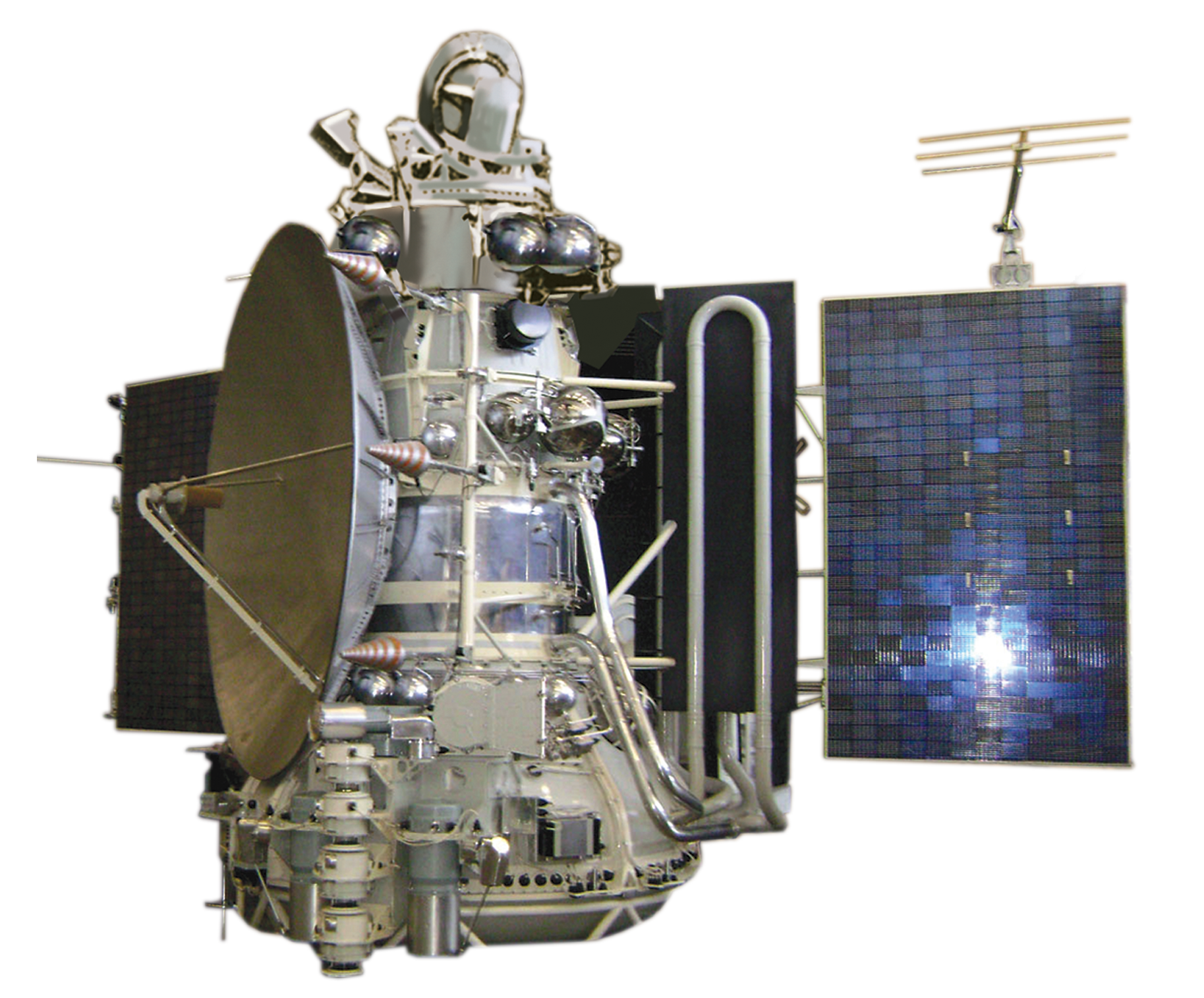
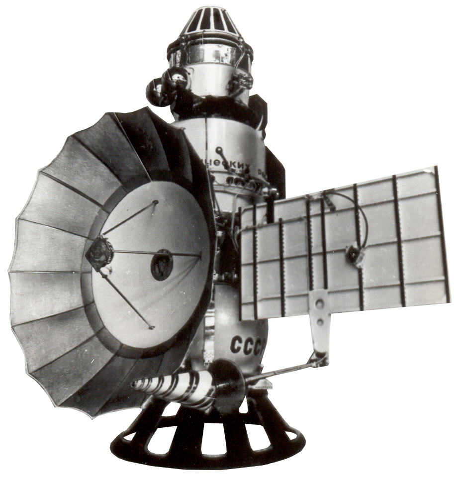
The Venera-4 automatic interplanetary station was developed on the basis of 3MV stations, designed at OKB-1 under the management of Sergey Korolev. The 3MV stations were intended to explore Mars and Venus both fr om a flyby trajectory and with a lander delivered on the planet's surface. The stations were being successfully tested for flight during the period from November 11, 1963 to November 23, 1965. There were 9 launches during which the onboard systems tests took place, but for one reason or another none of the stations was ever able to explore Venus or Mars. The greatest success accrued to the Zond-3 automatic station, launched on July 18, 1965 to test the onboard systems; the station also photographed the back side of the Moon.
The last three automatic stations of this series were launched in November 1965 toward Venus. One of them remained in Earth’s orbit, while the Venera-2 stations, purposes of which included photographing the planet Venus and studying near-planet space from the flyby trajectory, and Venera-3 with the descent module entered the interplanetary trajectory. However, they ceased communicating shortly before approaching Venus. This was caused by the onboard equipment overheating. In 1965 all works regarding manufacturing automatic interplanetary and lunar stations was transferred from OKB-1 to the MachineBuilding Plant named after Semen Lavochkin. Due to time constraints (the time left until another launch window in 1967 for flight to Venus comprised a bit more than one year), it was decided to lim it the design of the spacecraft only to deliver the descent module into the atmosphere of Venus.
Venera-3 was taken as the basis for the V-67 automatic stations, but based on the results of its flight some changes were made to its design. At the instrument compartment level, the orbiter underwent a radical redesign of the thermal control system (TCS): in substitution to the gas-liquid system, the design bureau engineers from the Lavochkin Machine-Building Plant developed the gas TCS, which was more reliable in terms of utilization and easier to produce. In addition, the TCS cooling radiator was combined with the central part of the parabolic high-gain antenna.
Due to the fact that since the launch of Venera-3 the Academy of Sciences had revised the model of the atmosphere of Venus and had provided within the statement of work for higher design values of temperature (425°C vs 330-350°C for Venera-3) and pressure (1-10 atm vs 1.5-5) near the planet's surface, the descent module had to be designed anew. At the same time, the tasks assigned to the Venera-4 interplanetary station sounded as follows: to entry the atmosphere of Venus to the maximum possible depth determined by the thermal resistance and strength of the SC; to attempt a landing on the planet's surface if the temperature and pressure limits are not reached; to transmit telemetric information during the entry into the atmosphere and after landing on Venus.
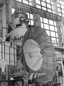
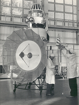
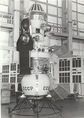
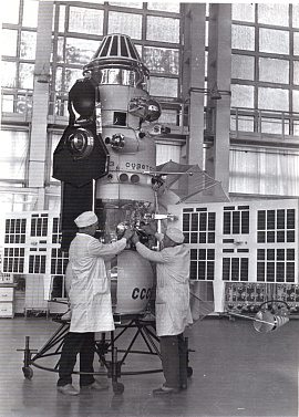
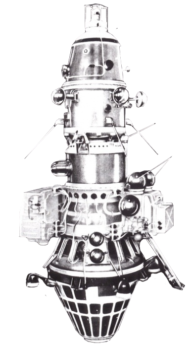
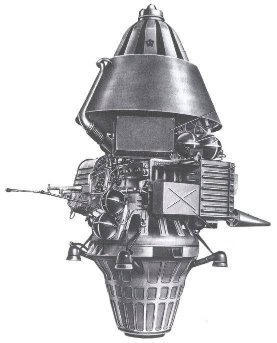
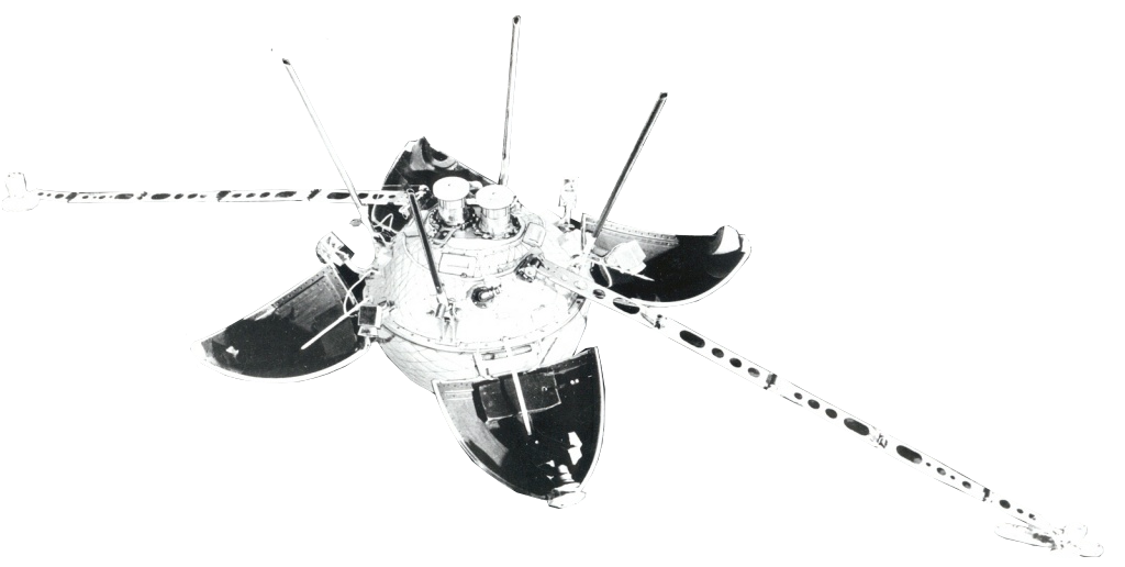
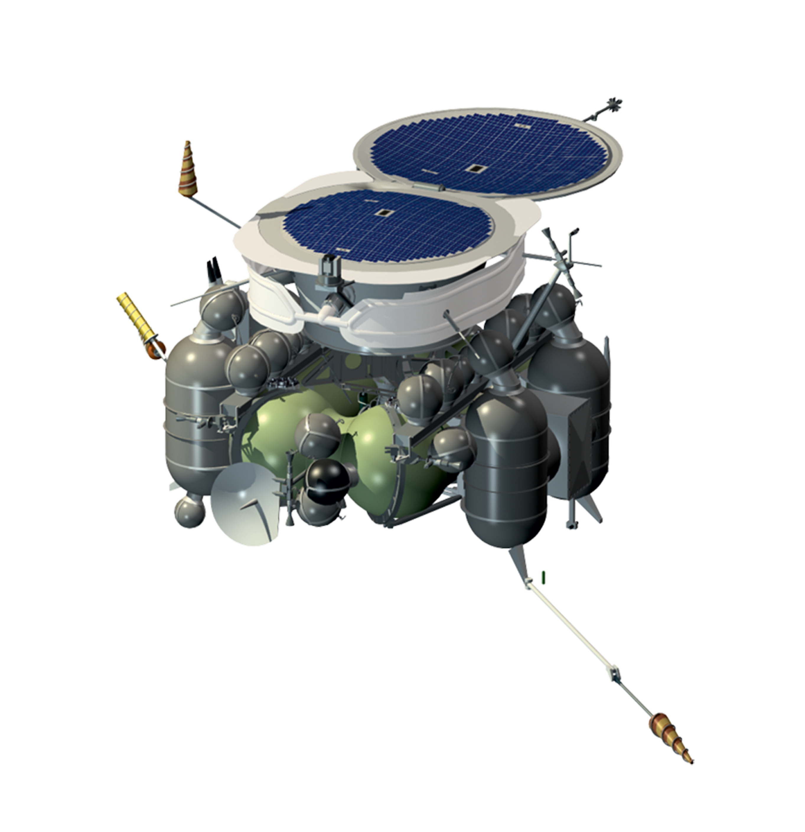
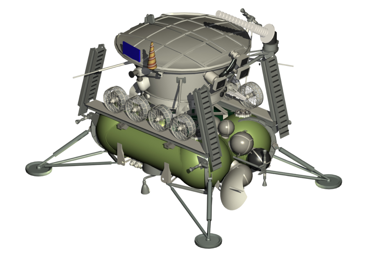
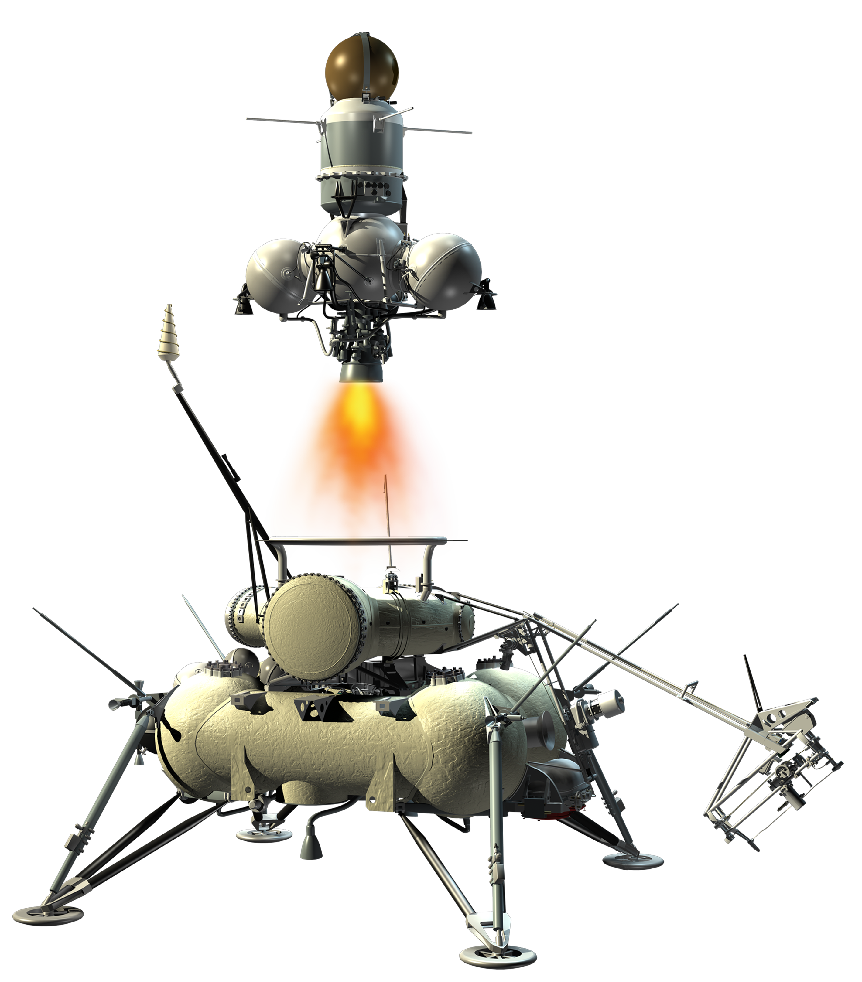
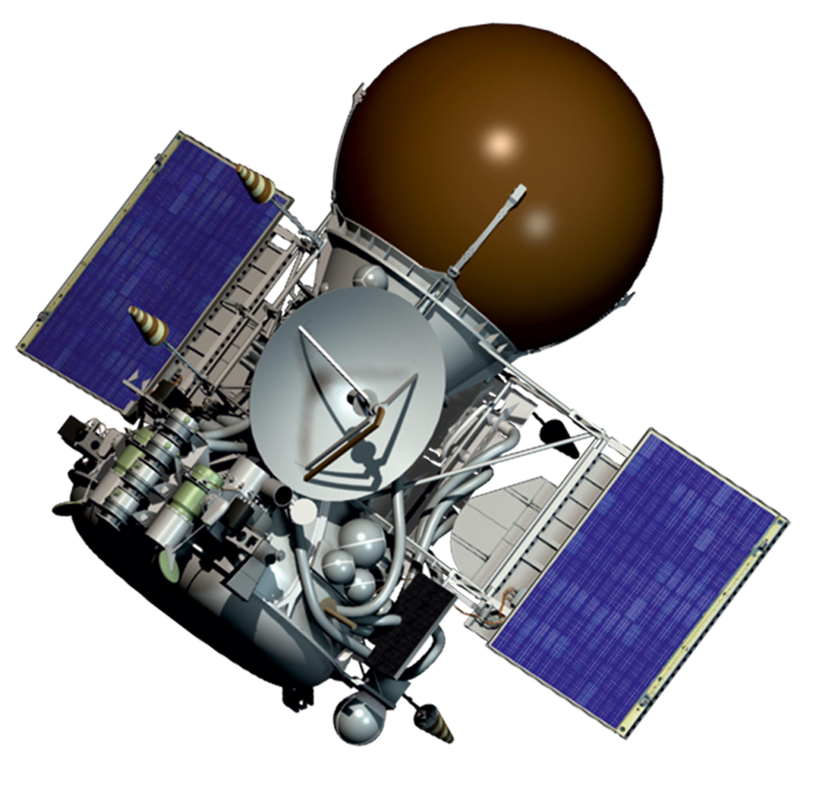
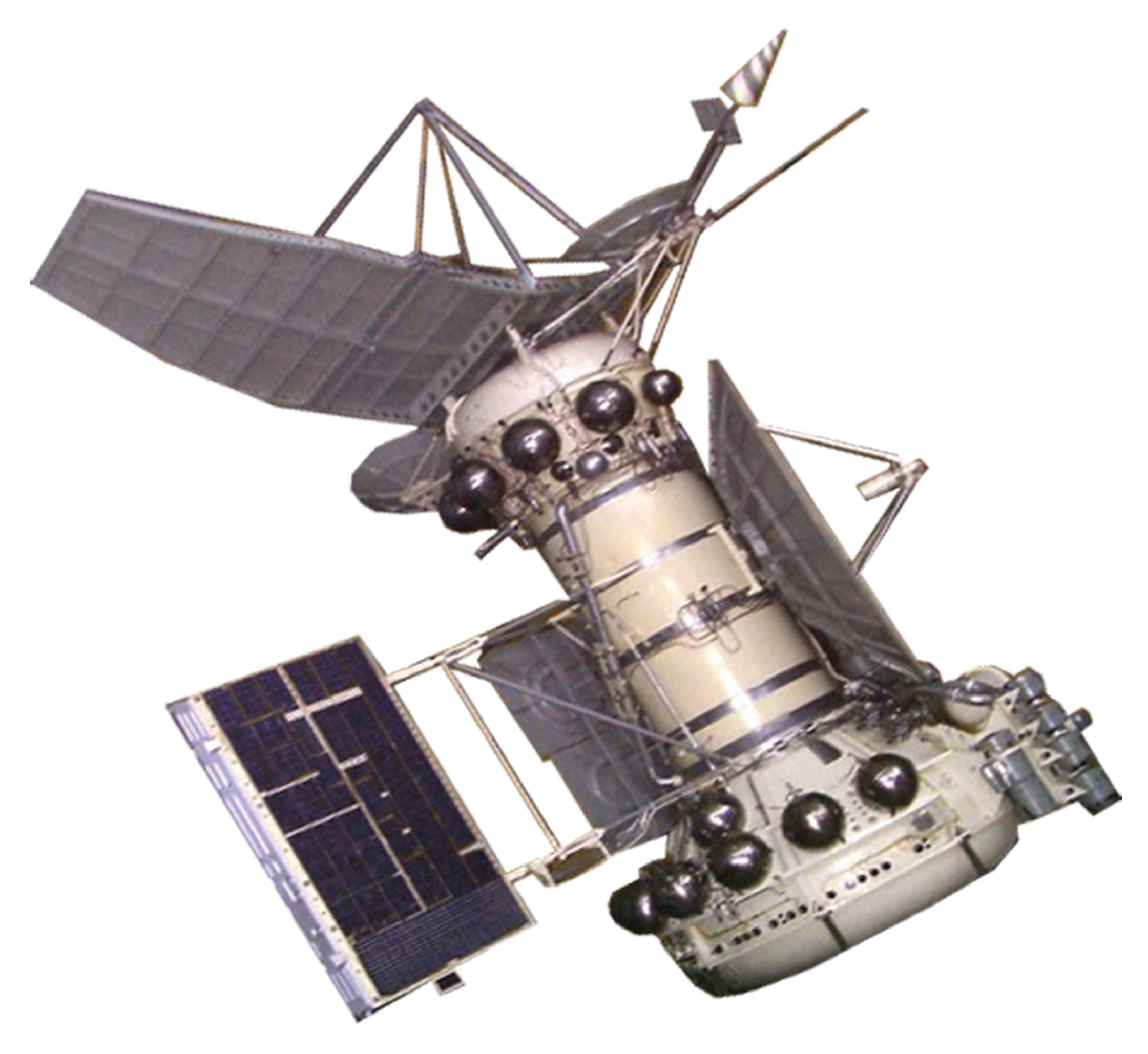
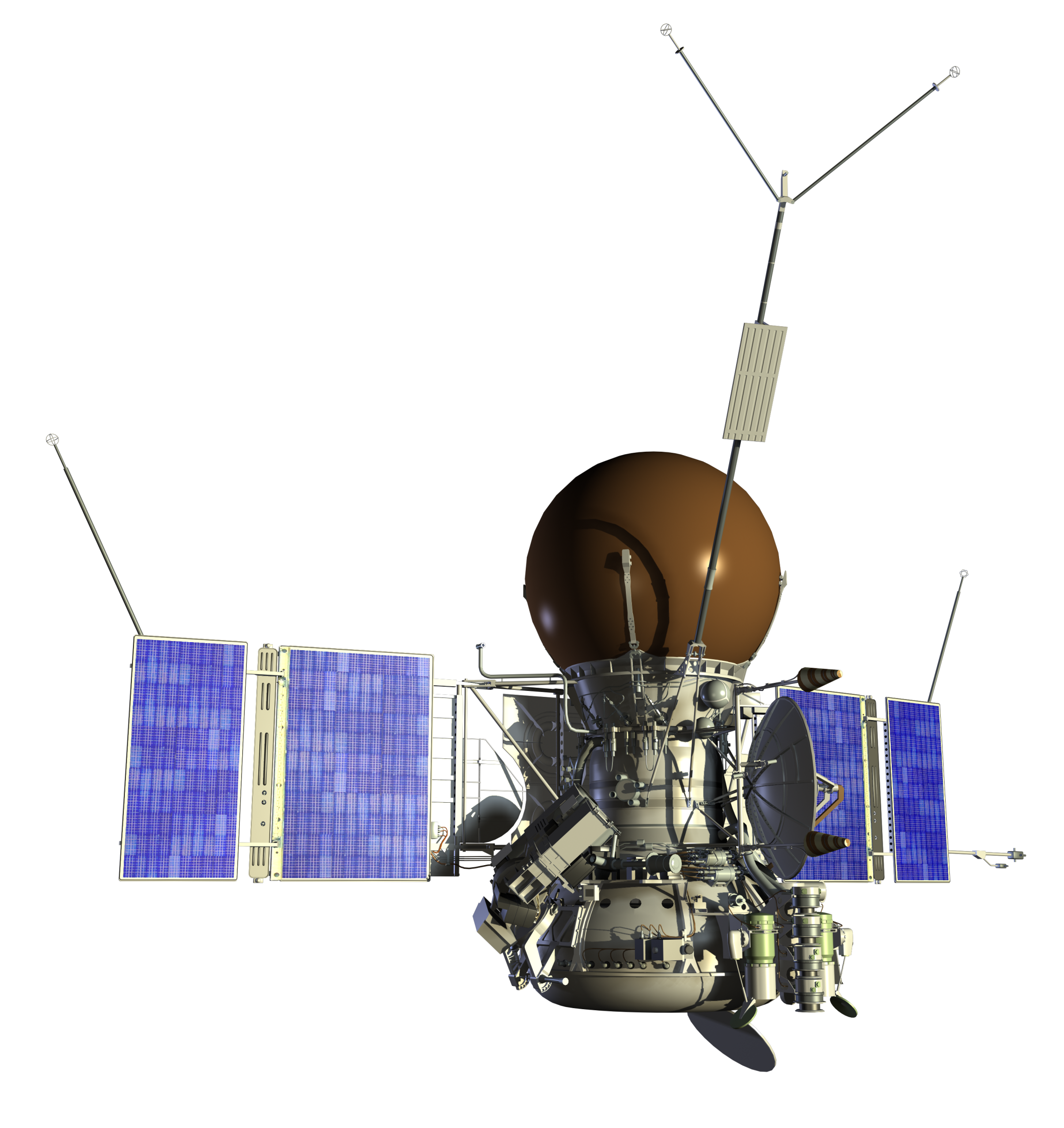
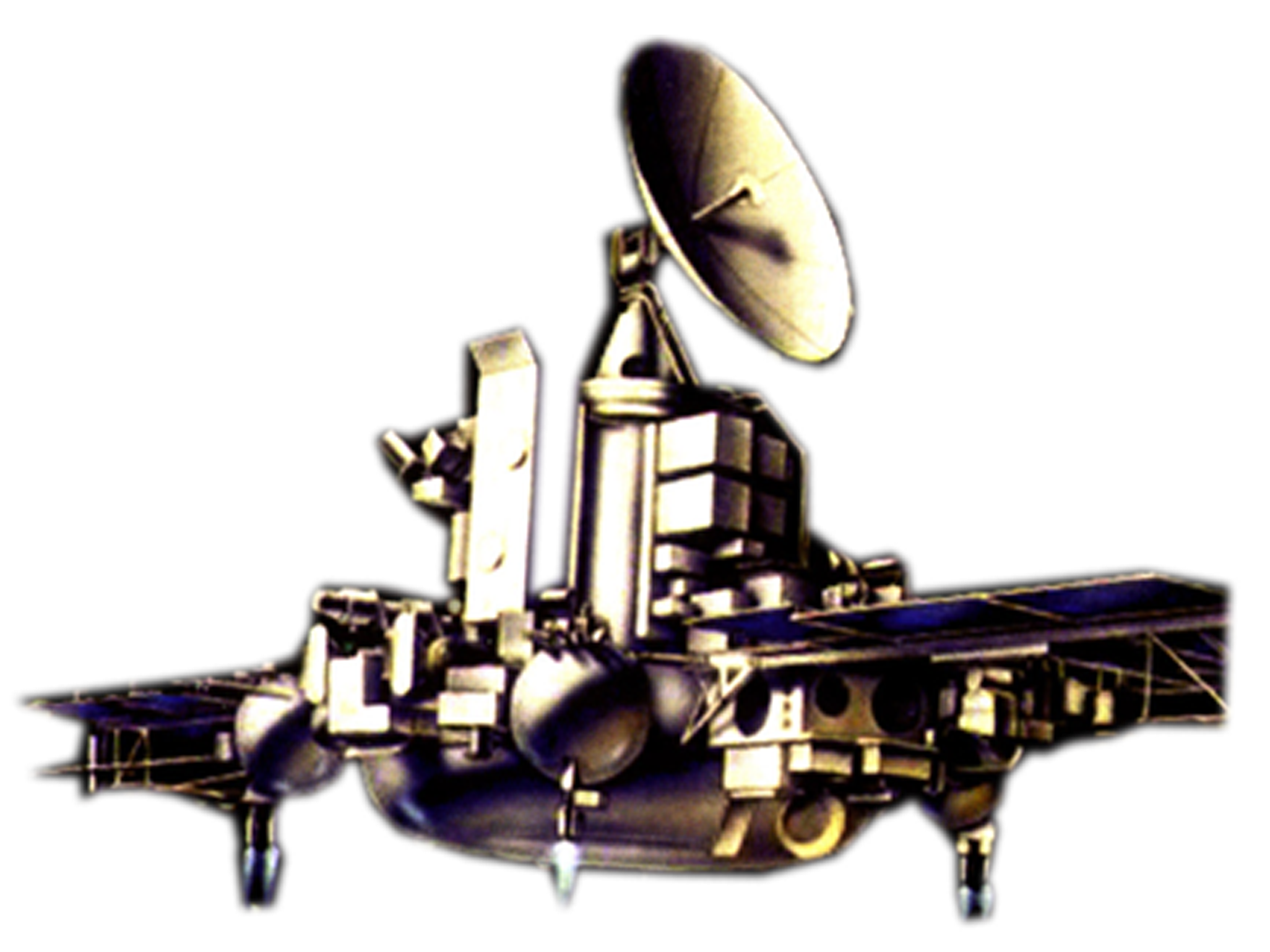
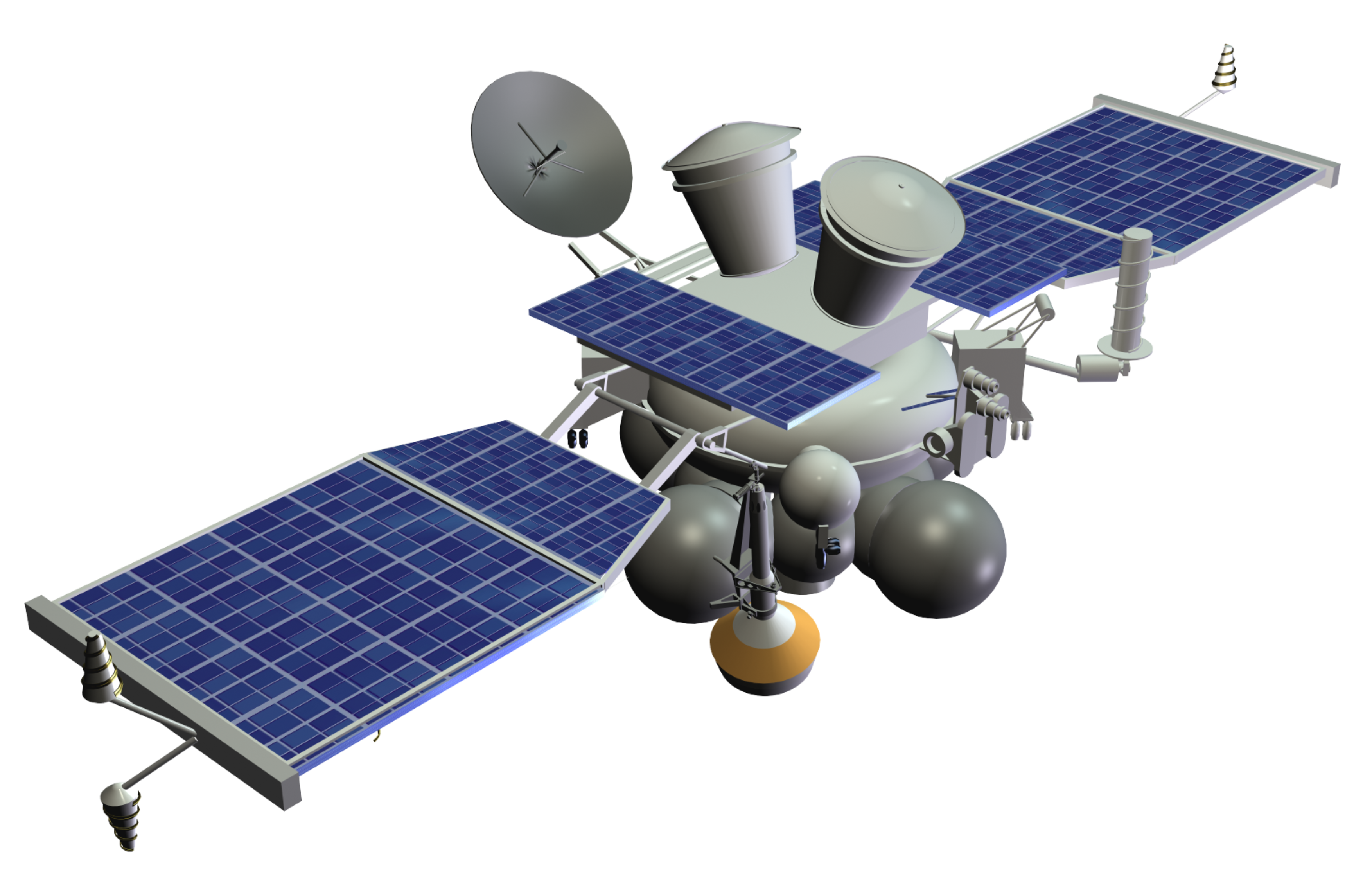
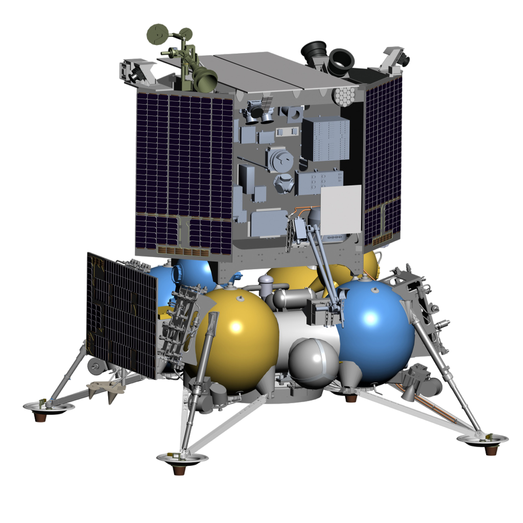
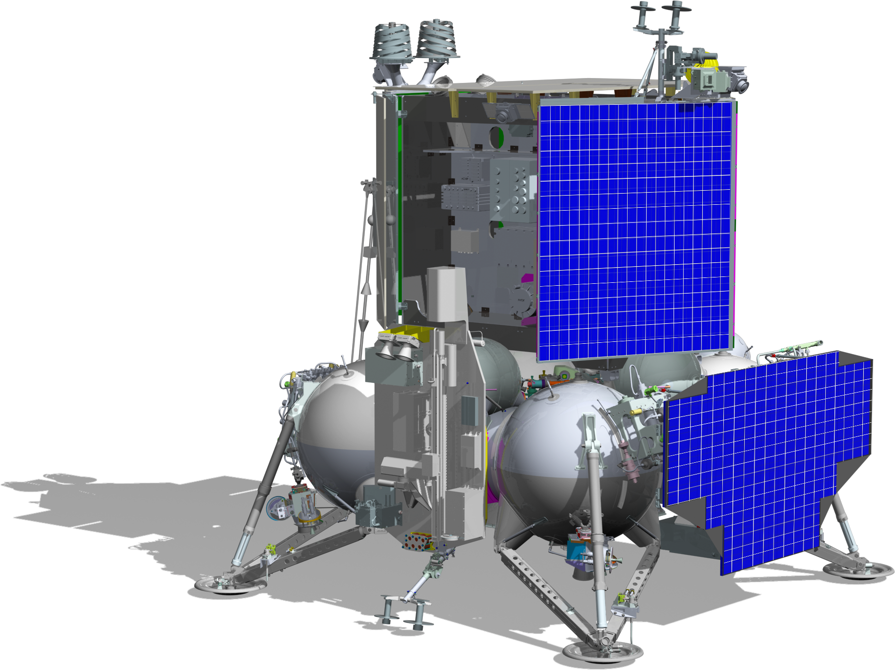
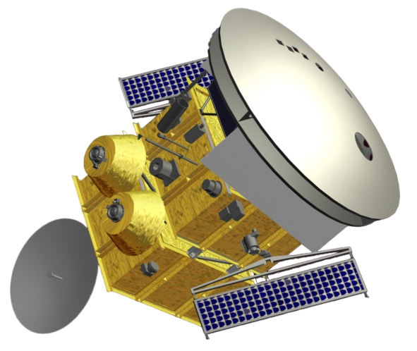
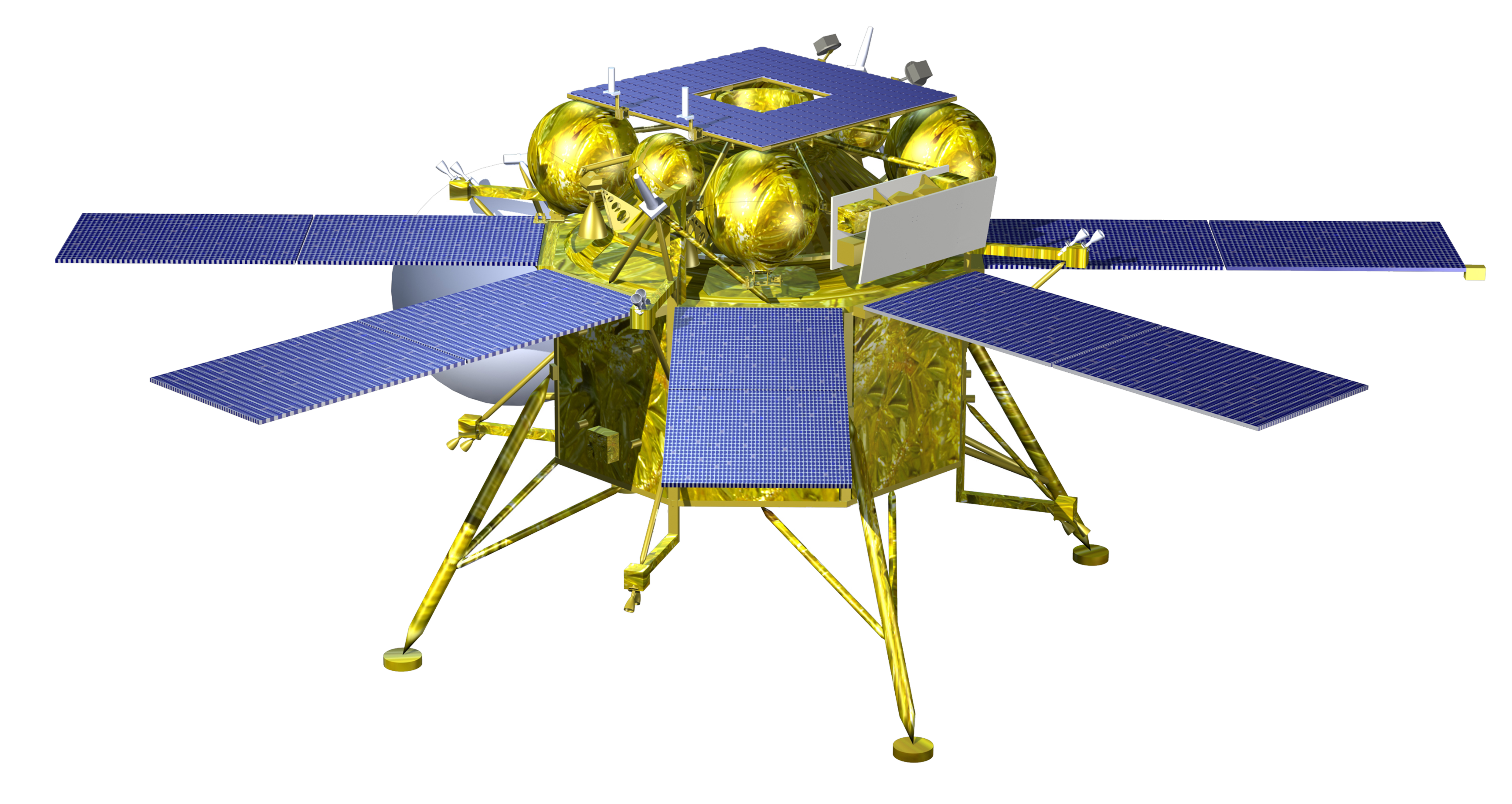
The Venera 4 Automated Station consisted of the descent module and the orbital compartment with a corrective propulsion system.
 The orbital compartment involved a sealed casing of cylindrical form, which contained radio frequency system instruments, Chaika-V star tracking and correction systems, thermal control system, batteries and scientific equipment.
The decimeter range radio frequency system was capable of receiving up to 127 commands from the Earth, making trajectory measurements and transmitting telemetry data to the Earth at rates of 1, 4, 16 and 64 bits per second. Power of the Dcm-band transmitter was 40 W.
Venera-4 used 6-bit telemetry with polling rates of 1, 4, 16, and 64 bps, which could work both in direct transmission mode and recording mode with subsequent reproduction. To record TM data in standby mode, the telemetry system included a tape recorder with a capacity of 150 thousand bits.
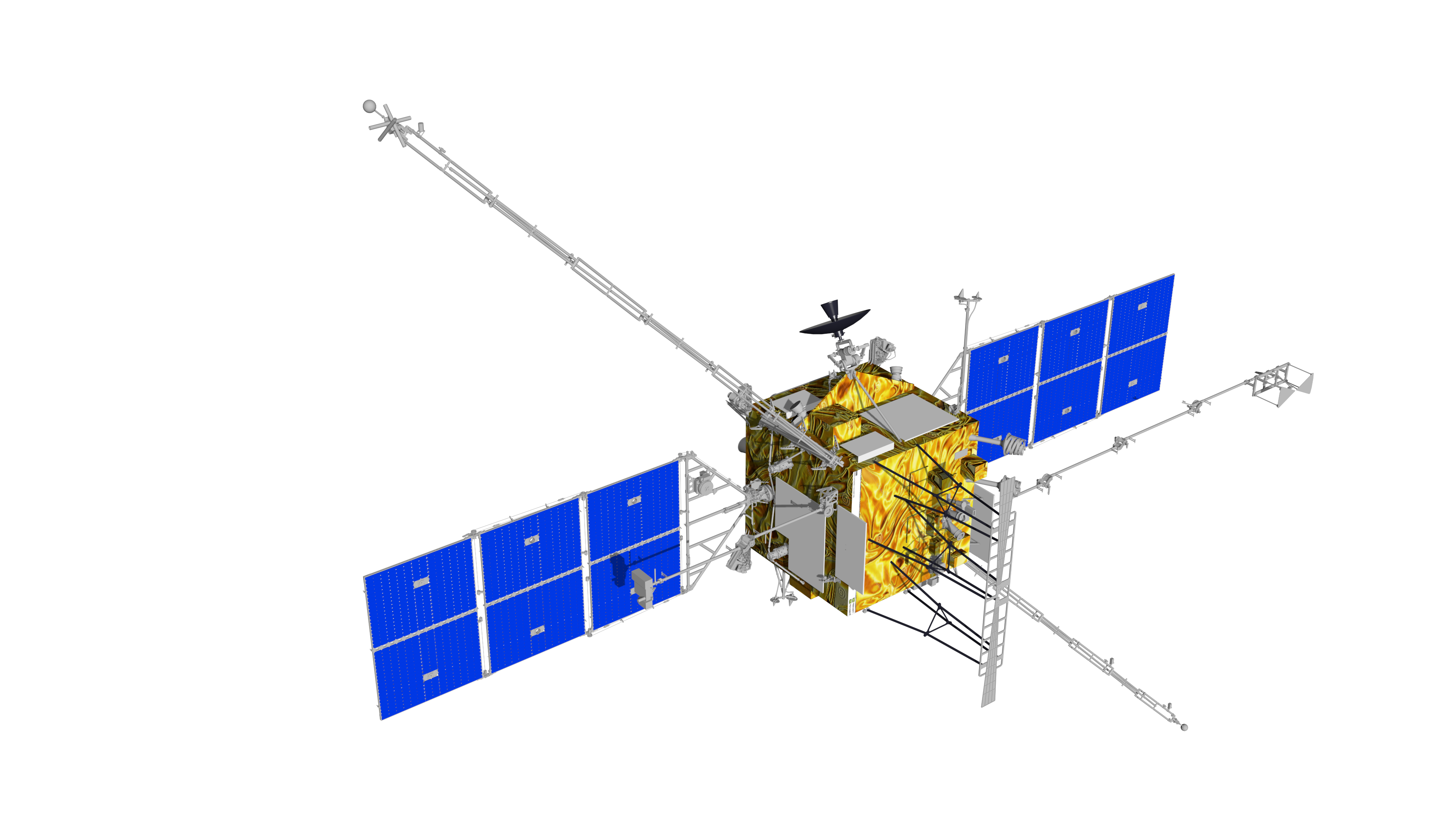
Newly developed Low Gain Antennas were used for radio communication. The transmission of information at the rate of 64 bits per second was realized via a parabolic high gain antenna (HGA) with a diameter of ~2.3 meters. The HGA consisted of a rigid central part with a built-in cooling radiator, and deployed during flight part, made of a metal mesh in the form of an umbrella. According to the ballistic conditions, the HGA can be used only after 45 days of flight.
The onboard equipment also included a program timing device, which ensured the issuance of tags to onboard systems at a specific time.
The Chaika-V attitude correction system was intended to provide constant solar orientation at coasting sections of the flight, pointing of the HGA to the Earth during communication sessions, building a threeaxis orientation before the trajectory correction to set the adjusting PS into a given direction and stabilizing the spacecraft during the correction.
A coarse solar tracker (+10° accuracy of constant solar orientation), a solar-stellar tracker unit, a solarterrestrial device ensuring HGA pointing to the Earth with an accuracy of ±40 angular minutes, a Venus detector and angular rate sensors operated as attitude correction system sensors.
At the beginning of the correction session, a three-axis orientation (the accuracy of the solar-stellar orientation was +6 angular minutes) is built with the help of the solar-stellar tracker unit, which is intercepted then by the gyrostabilized platform. The engine is switched on by the program timing device mark and switched off by the integrator when the desired correction rate is set.
If it is not possible to work with the star instrument, the so-called solar correction is performed. In this case, the sustainer nozzle is directed either towards the Sun, or in the opposite direction.
Nitrogen gas-fueled jet nozzles were used as the attitude and correction system actuators. Upon the adjusting PS operation, the pitch and yaw stabilization was realized by pumping the chamber of the liquid propellant engine.
The onboard equipment of the orbiter was powered by the substantially redesigned power supply system. It consisted of two solar array panels with a total area of 2.4 m2 . A cadmium-nickel battery with a nominal capacity of 84-amp hr. was used as a buffer battery of the main compartment.
The thermal control system ensured gas circulation in the orbital compartment by means of a fan, while heat was discharged through a cooling radiator built into the HGA. Temperature regulation within set limits was provided by a flap valve that opened and closed the air supply line to the cooling radiator.
The external side of the orbital compartment contains optical sensors and actuators of the stellar orientation system, two deployable solar array panels, LGA and HGA of the radio frequency system, the magnetometer boom and sensors of scientific instruments.
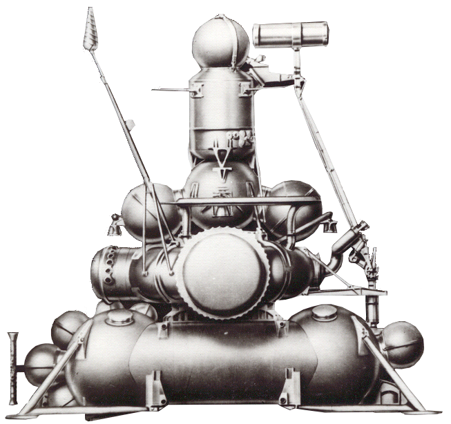
The rear part of the pressurized compartment was attached with an unpressurized section of the adjusting PS supplied with a liquid propellant engine, as well as spherical tanks with propellant components (nitrogen tetroxide and unsymmetrical dimethylhydrazine) and supply system, nozzles of gas-fueled correction engines. It was supposed to have two trajectory corrections during flight.
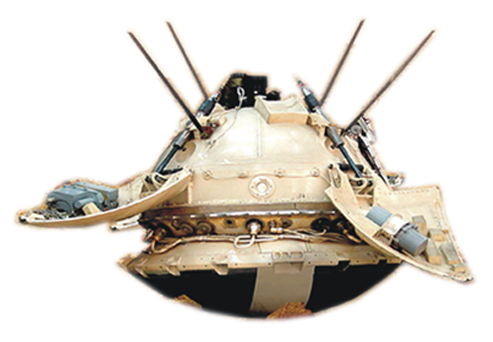
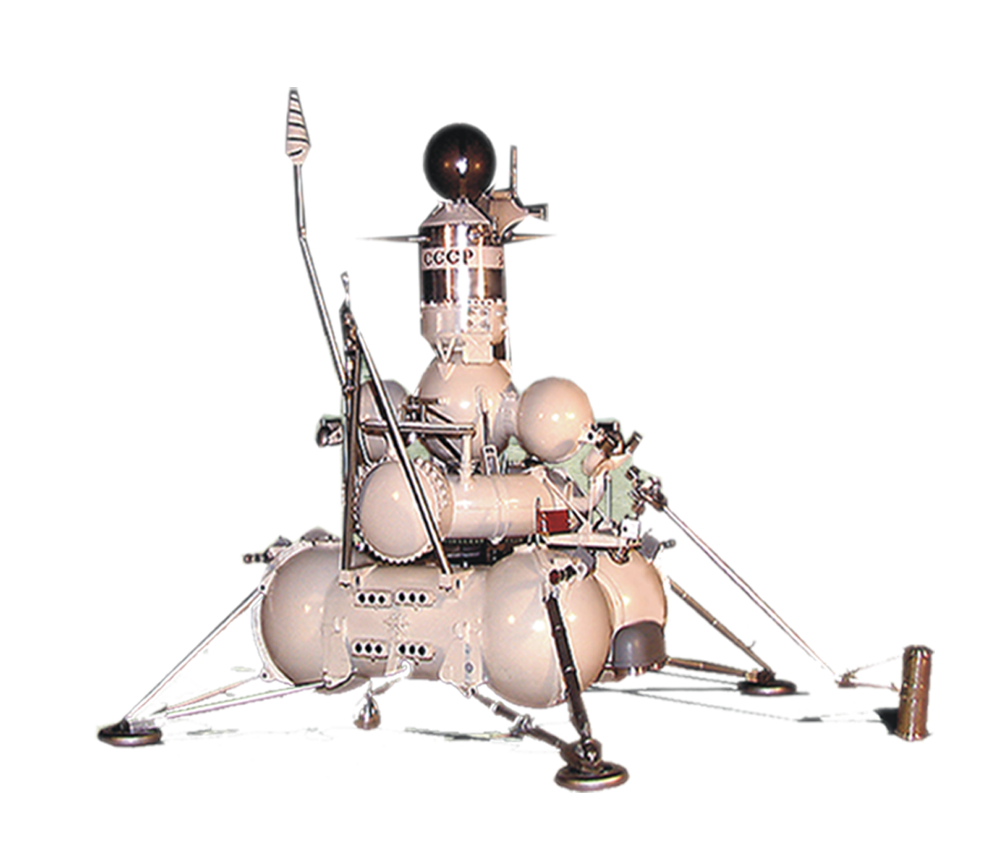
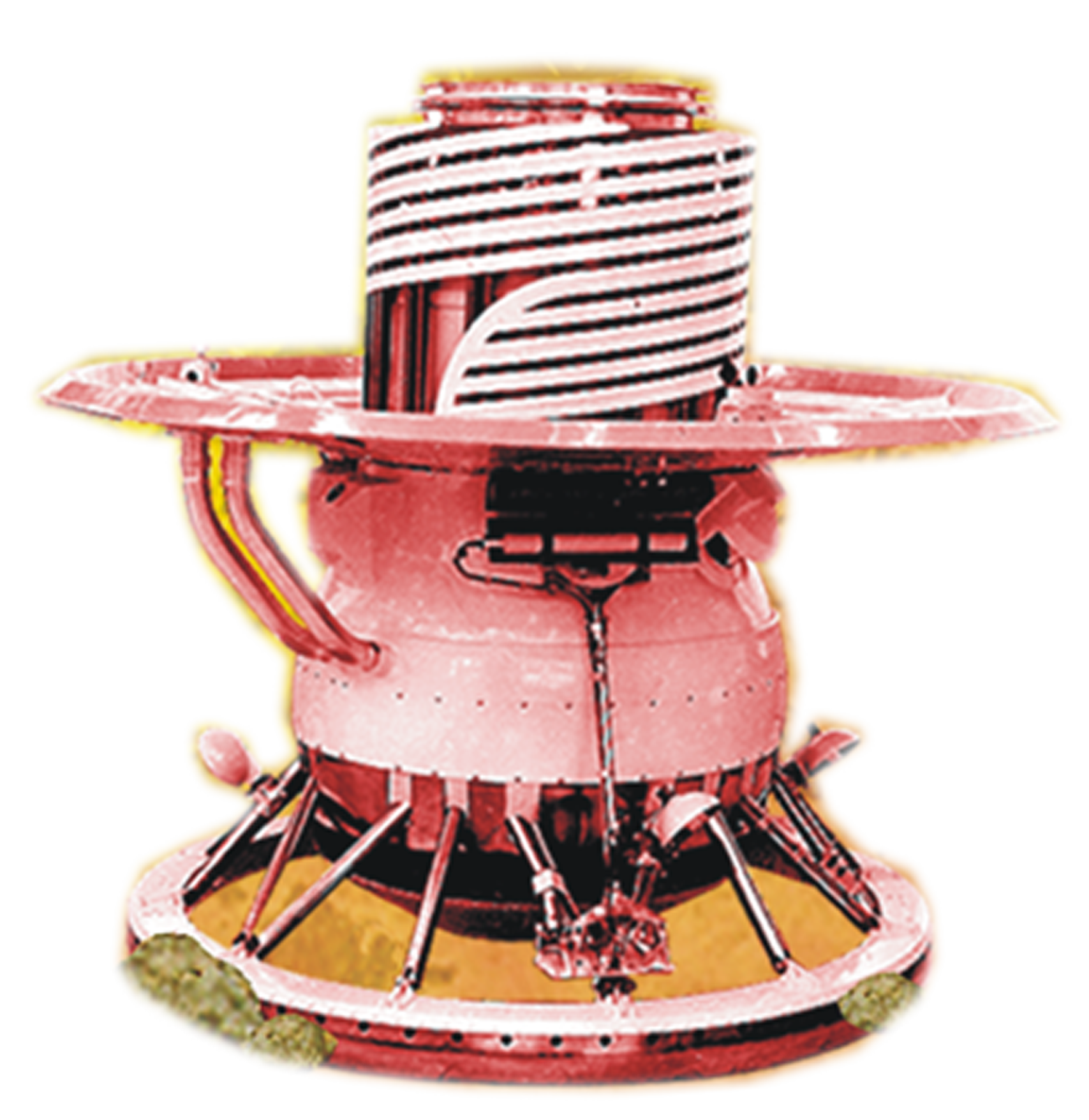
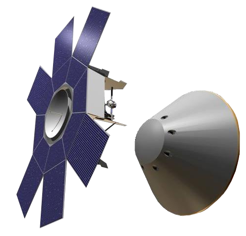
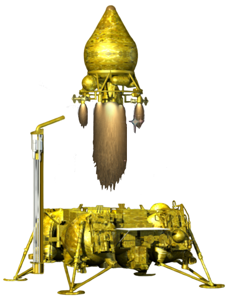
Descent module
The main payload of the Venera-4 automated station was the descent module, installed in the head of the spacecraft and attached to the main compartment with fixing straps.
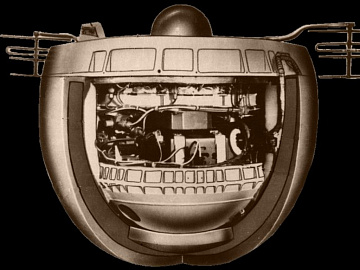
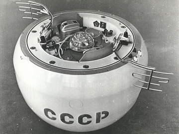
The module had a shape close to a balloon with a diameter of 103 cm. Structurally the descent module consisted of two pressurized compartments: instrument and parachute ones. There was a mechanical damper installed in the lowest part of the descent module, reducing oscillations during movement inside atmosphere after the module separation from the orbital compartment.
The parachute compartment was equipped with a two-stage parachute system consisting of a brake parachute with a canopy of 2.2 m² in area and a main parachute with a canopy of 55 m² in area. To determine the moment of parachute injection and opening, the overload sensors, pressure transducers and timing mechanism were used.
The same compartment housed the decimeter transmitter antennas and radio altimeter, the lid separation system and the parachute opening and decoupling system. The antennas deployment took place upon the main parachute unfolding. The Vysota (Eng.: Height) radio altimeter is designed to mark five fixed heights: 26; 14; 9; 4,5 and 2 km above the surface of the planet and to link to them temperature, density, pressure data and chemical composition of the atmosphere.
 The instrument compartment housed instruments for service onboard systems, including a decimeter range radio frequency system, telemetry system, electric automated units and thermal control systems. To power service and scientific instruments in the descent module, a 28-amp hr. chemical battery was installed, which was supplied during flight with a small current from a separate section of the solar array to prevent self-discharge. The battery was designed for about 100 minutes of continuous operation.
The transmitter used in the radio frequency system of the descent module was the same as of the orbital compartment. Telemetry and scientific data was transmitted directly from the descent module to the Earth. However, given the distance from Venus and considering the fact that scientific data was transmitted via the LGA, the transmission rate comprised only 1 bit per second. In case of failure of one transmitter, a special device was supposed to automatically connect a redundant set.
In order to increase stiffness of the descent module, there was ensured a gas pressure of 2 atmospheres inside the instrument compartment.
The exterior of the descent module was covered with thermal protection involving sublimation materials. Compared to Venera-3, the thermal protection was considerably reinforced. To prevent the spacecraft from heating up during descent, a multi-layer insulation made of glass-textolite honeycomb with textile and asbestos laminate insertions was installed between the external thermal protection and the body.
Before launch, the descent module had been sterilized to prevent the introduction of bacteria from the Earth to Venus.
The total mass of the Venera-4 automatic station comprised 1106 kg. Since the spacecraft was much heavier than Venera-3 (960 kg), it was launched with an upgraded 8K78M launch vehicle (Molniya-M) with the VL upper stage instead of the 8K78 rocket (Molniya).